So, thought I'd start this compilation of posts, each one covering a different component of the wiring. Should be good for '70-'71, most '69, and may be of value to other years as well.
First - the Headlight Switch
The headlight switch, whether stock Mopar or aftermarket, is designed to transfer power from two power inputs (B-1 and B-2) to various circuits depending on the position of the switch. The switch can be "Off/fully in"; "Parking/halfway/pulled out one stop"; or "On/fully out". Using a multimeter, here's what I find...
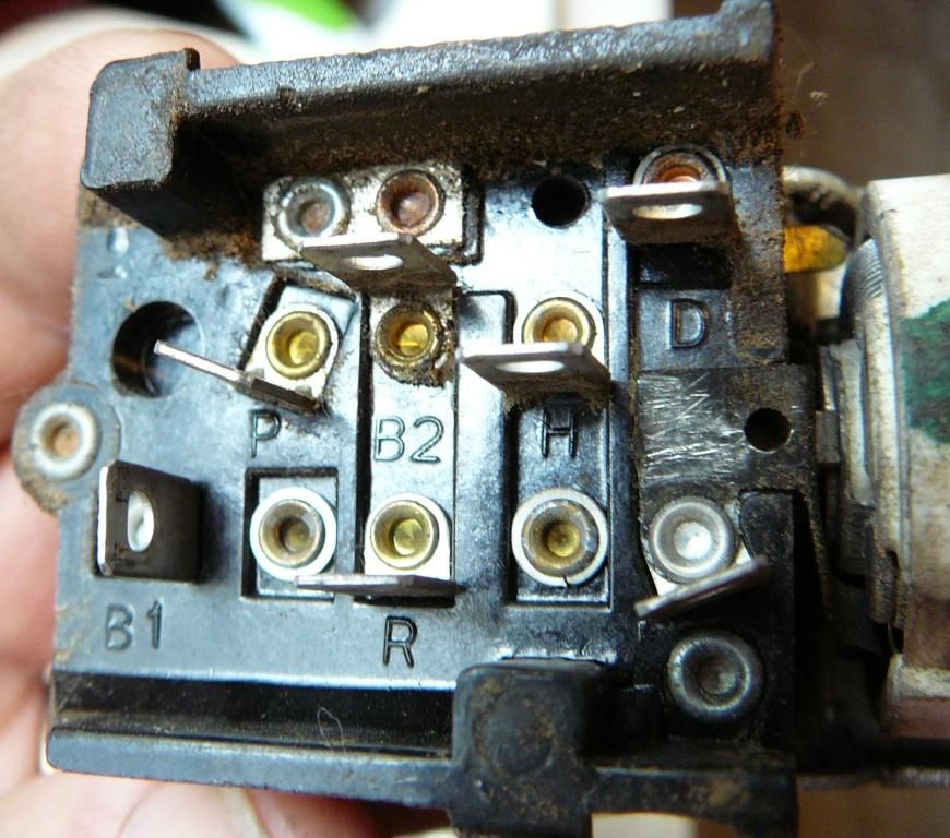
Looking at a couple of wiring harnesses and switches, and working counter-clockwise from the lower left of the pictured switch:
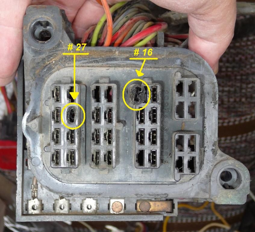
B1 - large Dark Blue (12 ga.) [power IN from the non-fused Alternator wire, the big black one coming in from the bulkhead connector #16.]
This powers only the H circuit when the switch is ON/pulled fully out.
R - Brown (16 ga.) AND Dark Green (18 ga.) wires (in my harnesses), but only Brown in wiring diagram [Brown is the Running Lights circuit. The Dk Grn wire being here allows the parking lights to be ON when the headlights are on, too... see "P" at bottom.]
This gets power from only the B-2 feed, when the switch is either in the Parking/halfway position or in the ON/full out position.
I - Tan (18 ga.) [Instrument Lights, dims on rotation of rheostat in switch]
This also gets power from only the B-2 feed, when the switch is either in the Parking/halfway position or in the ON/full out position.
H - Yellow (16 ga.) {Headlight Circuit, goes to the dimmer switch]
This gets power from only the B-1 feed, when the switch is in the ON/full out position.
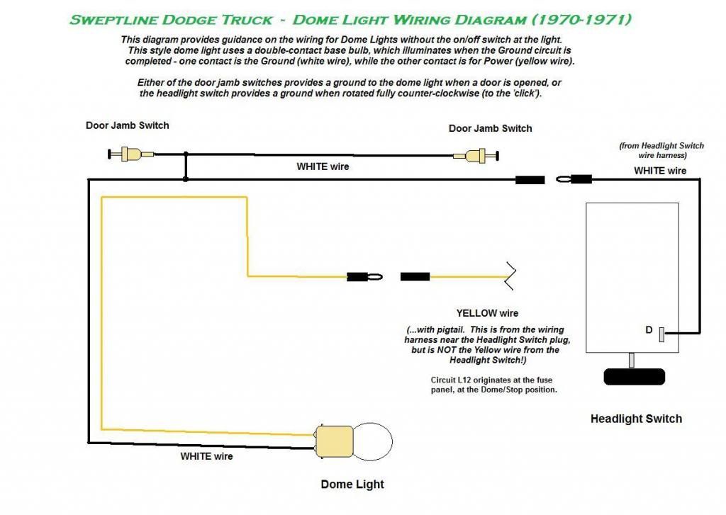
D - White (18 ga.) [Dome Light ground; this serves to provide a ground/negative source through the white wire to the double-contact-base dome light bulb, which operates by one contact receiving negative/ground, and the other receiving positive 12VDC power through the yellow wire]
This does not get any power, but is grounded only when the switch is rotated fully counter-clockwise ('click'), flipping a grounding tab below the terminal, behind the ceramic rheostat disc.
B2 - large Red (12 ga.) [Power IN from the Battery, via the Tail, Park and Side-Marker Lights 20amp fuse in fuse panel]
This powers the R, I and P circuits when the switch is in the Parking/halfway position; and only the R and I circuits when ON/pulled fully out.
P - no wire in my harnesses, but Dark Green in wiring diagram - see "R" above [Parking LIght circuit].
This gets power from only the B-2 feed, and only when the switch is in the Parking/halfway position.
