Page 1 of 2
'70 "Alternate" Ammeter wiring help anyone?
Posted: Sun Oct 27, 2013 3:53 pm
by PwrWgnWalt
Hi all;
Seems Dodge recognized the weakness of passing full ALT/BATT current through their bulkhead connector by the last years of these trucks, and had a fix I want to duplicate on my '70 W200 while it is apart.
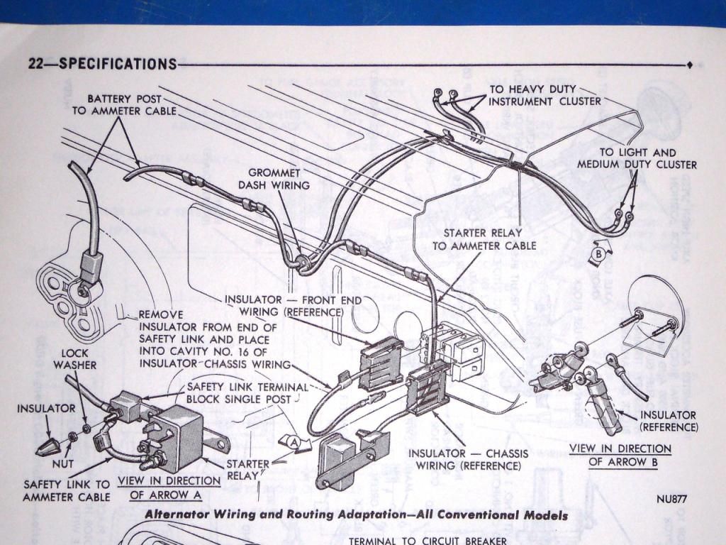
Have deciphered most of what I need to do from the back of the Service Manual for '69-'71, on page 22-SPECIFICATIONS, "Alternator Wiring and Routing Adaptation". This shows heavy wires passing directly through the firewall to the ammeter from both the alternator (black), and an additional post terminal off of the starter relay (red) - no terminals, no connections except at each end. Also see that the regular bulkhead wiring connector slots 16 and 27 (the ones that are always melted) get bridged just inside the engine compartment.
However, I am perplexed by one thing: what does one do with the
existing ammeter (stock location) connections? It appears by the diagram that maybe the existing red wire stays attached to the ammeter (and thereby gets power)... but what about the black wire??
If anyone has this factory setup and can tell me exactly how the wiring is set up at the ammeter, I would be most grateful!
Thanks in advance,
- PwrWgnWalt

Re: '70 "Alternate" Ammeter wiring help anyone?
Posted: Sun Oct 27, 2013 4:46 pm
by soopernaut
Dodge used the faulty wiring through the 70s and perhaps into the 80s as well. I'm surprised there would be a fix in a 69-71 manual unless it was written much later.
Re: '70 "Alternate" Ammeter wiring help anyone?
Posted: Sun Oct 27, 2013 5:45 pm
by PwrWgnWalt
Here's the page... don't know when the book was printed: (click for full view)
Re: '70 "Alternate" Ammeter wiring help anyone?
Posted: Sun Oct 27, 2013 10:21 pm
by PwrWgnWalt
The original black wire in the engine bay, from the bulkhead connector to the alternator, gets replaced with a direct-to-ammeter heavy gauge wire (alternator direct to ammeter = black).
The original red wire in the engine bay, from the bulkhead connector to the starter relay, gets replaced with a direct-to-ammeter heavy gauge wire too, and there is a small terminal block added at the starter relay to accept this new wire (ammeter to starter relay = red)
From this new piece, the terminal block, a fusible link connects the new heavy gauge RED wire to the starter relay, providing protection for the circuit.
A new fusible link bulkhead connector bridge (across slots 16 & 27 on the engine side of the bulkhead connector) provides power to both sides of the original interior black-wire circuit (alternator) and red-wire circuit (battery), so everything still works like it was designed.
In lieu of a member having an actual example of the 'adapted' setup, can anyone see a fault in this thinking?
PwrWgnWalt
Re: '70 "Alternate" Ammeter wiring help anyone?
Posted: Sun Oct 27, 2013 11:58 pm
by MrMopar
My 1969 CHP Dodge Polara has this wiring but it apart for restoration.
Not sure what the question is, the drawing looks pretty clear to me.
Alan
Re: '70 "Alternate" Ammeter wiring help anyone?
Posted: Mon Oct 28, 2013 6:01 am
by wally426ci
Integrating. Also could convert to a volt meter....
Re: '70 "Alternate" Ammeter wiring help anyone?
Posted: Mon Oct 28, 2013 8:58 am
by PwrWgnWalt
PwrWgnWalt wrote:
However, I am perplexed by one thing: what does one do with the
existing ammeter (stock location) connections? It appears by the diagram that maybe the existing red wire stays attached to the ammeter (and thereby gets power)... but what about the black wire??
If anyone has this factory setup and can tell me exactly how the wiring is set up at the ammeter, I would be most grateful!
Thanks in advance,
- PwrWgnWalt
Hi Alan and all,
I am trying to find out what I need to do with the existing (stock) wiring that goes to the ammeter; I don't find this explained clearly in the diagram.
Thanks,
Re: '70 "Alternate" Ammeter wiring help anyone?
Posted: Mon Oct 28, 2013 4:18 pm
by MrMopar
PwrWgnWalt wrote:PwrWgnWalt wrote:
However, I am perplexed by one thing: what does one do with the
existing ammeter (stock location) connections? It appears by the diagram that maybe the existing red wire stays attached to the ammeter (and thereby gets power)... but what about the black wire??
If anyone has this factory setup and can tell me exactly how the wiring is set up at the ammeter, I would be most grateful!
Thanks in advance,
- PwrWgnWalt
Hi Alan and all,
I am trying to find out what I need to do with the existing (stock) wiring that goes to the ammeter; I don't find this explained clearly in the diagram.
Thanks,
It still goes to the ammeter, all this does is remove the heavy current from the bulkhead connector.
Alan
Re: '70 "Alternate" Ammeter wiring help anyone?
Posted: Mon Oct 28, 2013 6:52 pm
by Roxyflash
What I did was pull the terminals from the buckhead then I just pulled a 10 gauge wire tru the buckhead with some silicone right stuff to seal it.Got rid of the original wires and hard wired it straight tru .Simple effective.
Re: '70 "Alternate" Ammeter wiring help anyone?
Posted: Tue Oct 29, 2013 11:28 pm
by PwrWgnWalt
Ok, so if I understand all this correctly, I should be OK to run the new wires as follows:
8 ga. BLACK - from alternator "BATT" terminal straight thru firewall to 'charge' post of the ammeter.
8 ga. RED - 12 ga. fusible link from large 3/8" post on Starter Relay, to single terminal block post (new), with 8 ga. red wire going from there straight thru the firewall to the 'discharge' post of the ammeter. I will then bridge the bulkhead connector slots 16 and 27, per the diagram.
I will leave the existing black and red wires behind the dash hooked up to the ammeter per the oem wiring.
Leaving the wiring will leave the ammeter functional; the load side wiring (the original black wire) that goes to the fuse panel, ignition switch, and headlight switch, and will cause the ammeter needle to deflect to 'charge' when there is current being supplied by the alternator in excess of system use...
While the original red wire (essentially from the battery, via the starter relay) will deflect the needle to 'discharge' when that condition exists and the system is using more current than is being supplied by the alternator.
Unless someone finds a valid fault in my thinking, this will be the plan.
I will take some pictures of the adaptation and post soon.
-Walt
Re: '70 "Alternate" Ammeter wiring help anyone?
Posted: Wed Feb 25, 2015 10:32 am
by BAD1DAN
This is what I have been looking for! My 71 d100 has this setup and I have been trying to figure out if it was right. Now my only question is if the negative field ground needs to be grounded somewhere specific?
Re: '70 "Alternate" Ammeter wiring help anyone?
Posted: Wed Feb 25, 2015 1:20 pm
by nytemuvr
PwrWgnWalt wrote:The original black wire in the engine bay, from the bulkhead connector to the alternator, gets replaced with a direct-to-ammeter heavy gauge wire (alternator direct to ammeter = black).
The original red wire in the engine bay, from the bulkhead connector to the starter relay, gets replaced with a direct-to-ammeter heavy gauge wire too, and there is a small terminal block added at the starter relay to accept this new wire (ammeter to starter relay = red)
From this new piece, the terminal block, a fusible link connects the new heavy gauge RED wire to the starter relay, providing protection for the circuit.
A new fusible link bulkhead connector bridge (across slots 16 & 27 on the engine side of the bulkhead connector) provides power to both sides of the original interior black-wire circuit (alternator) and red-wire circuit (battery), so everything still works like it was designed.
In lieu of a member having an actual example of the 'adapted' setup, can anyone see a fault in this thinking?
PwrWgnWalt
:usa
Has worked like that on my Challenger for at least 20 years, even though the firewall connectors are different and wiring is a little differnt.
Re: '70 "Alternate" Ammeter wiring help anyone?
Posted: Wed Feb 25, 2015 1:44 pm
by BAD1DAN
Hey nytemuvr, can you look to see where your negative field terminal from your alternator is grounded?
Re: '70 "Alternate" Ammeter wiring help anyone?
Posted: Wed Feb 25, 2015 8:54 pm
by 66patrick
soopernaut wrote:Dodge used the faulty wiring through the 70s and perhaps into the 80s as well. I'm surprised there would be a fix in a 69-71 manual unless it was written much later.
Not quite...Chrysler stopped this on cars across the board in the 1975 model year. In trucks, it was the 1979 model year that they quit that straight-to-the-ammeter nonsense.
Here is a great link that you can use in bypassing a broken or defective ammeter, or reduce the voltage going to a good one. The example shown is a 1967 Chrysler New Yorker, but the wiring basics concerning the ammeter DO apply.
http://cbodydrydock.com/e107_plugins/fo ... .php?67917
Re: '70 "Alternate" Ammeter wiring help anyone?
Posted: Wed Feb 25, 2015 11:51 pm
by nytemuvr
BAD1DAN wrote:Hey nytemuvr, can you look to see where your negative field terminal from your alternator is grounded?
It grounds itself to the engine, no wire.
Re: '70 "Alternate" Ammeter wiring help anyone?
Posted: Thu Feb 26, 2015 5:37 pm
by BAD1DAN
nytemuvr wrote:BAD1DAN wrote:Hey nytemuvr, can you look to see where your negative field terminal from your alternator is grounded?
It grounds itself to the engine, no wire.
I have the new style square back alternator has two field wires and I have the old style VR in my 71. I just grounded it to the firewall. It's charging anywhere from 13.5 to 16 volts. I had a cheap Chinese regulator on there and it was charging at 19, so it's better than it was but still needs work
Re: '70 "Alternate" Ammeter wiring help anyone?
Posted: Thu Feb 26, 2015 5:57 pm
by nytemuvr
BAD1DAN wrote:nytemuvr wrote:BAD1DAN wrote:Hey nytemuvr, can you look to see where your negative field terminal from your alternator is grounded?
It grounds itself to the engine, no wire.
I have the new style square back alternator has two field wires and I have the old style VR in my 71. I just grounded it to the firewall. It's charging anywhere from 13.5 to 16 volts. I had a cheap Chinese regulator on there and it was charging at 19, so it's better than it was but still needs work
Sorry, when you said Electronic Ignition I just assumed the VR was electronic too and a roundback (1 field wire) alternator....you know what they say about that word assume.
Re: '70 "Alternate" Ammeter wiring help anyone?
Posted: Sat Mar 07, 2015 7:43 pm
by pwadventurer
PwrWgnWalt wrote:
I will take some pictures of the adaptation and post soon.
-Walt
Hey Walt, how did the upgrade go, I see the post is a year and a half old, (that's like a few days in rebuild time). I wonder if the amp gauge moves much with the upgrade seeing the gauge is in parallel instead of series with the load. Attached is a diagram of the upgrade showing the wiring to the ammeter, might or might not help.
Re: '70 "Alternate" Ammeter wiring help anyone?
Posted: Sat Mar 28, 2015 9:20 pm
by archlab
Hiya,
Not that this all applies to what you're doing, but there might be something helpful in here:
I upgraded my entire Electrical Charging & Ignition system for 2 '67 & '68 Barracudas plus my '69 D100. I did not need to replace the coil. For what I did, these are some pretty helpful links below:
a) Wiring Diagram
http://www.mrmopar.com/1970DodgeTruck/w ... e-Full.png
b) MAD Electrical Guide:
http://www.madelectrical.com/electrical ... uges.shtml
c) AllPar Discussion & Guide to Electrical Upgrades:
http://www.allpar.com/history/mopar/electrical.html
Hope this stuff helps, I replaced the charging system with a later model Alternator & Voltage Regulator setup (used an alternator from a 1980's V8 on one & I think that I used an Alternator from a 2000's model Intrepid- yes, it was a Nippondenso - 90amp or so). I recommend the Nippondenso, as (at the time) the price was better & it fit fine. Also, I can definitely tell you guys that these were excellent improvements which eliminated any charging problems & got the power suitable for all my needs.
BTW, I highly recommend checking your wiring, esp. the Bulkhead COnnector (see Items b & c above). That is a real (if not THE) major electrical problem on Mopars in general.
Best to your upgrades, you'll be glad you did them.
Re: '70 "Alternate" Ammeter wiring help anyone?
Posted: Sun Mar 29, 2015 12:32 am
by 66patrick
What have you come up with? The MAD guide is probably the best explanation of how to cure the electrical ills these have.
