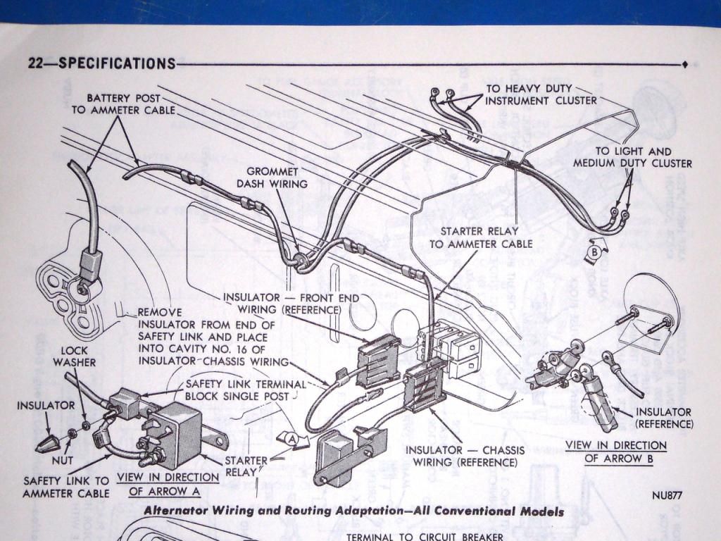
Here are the 4 Steps to doing this "Alternator Wiring Adaptation"... pretty simple, once I knew what to do. The scan of the Service Book page shows this all pretty well, it just didn't tell me what to do with the existing wiring at the Ammeter. (click pictures for full view)
1. Get heavy gauge wires to run the new lines. I used wires from a 1971 D200 Camper Special parts truck that had this done long ago; looks like either 8 or 6 ga. stranded wire. You use whatever fits your situation - at your own risk.
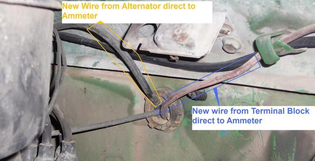
new BLACK wire- runs from the BATT post of the Alternator straight thru the firewall and to the Ammeter 'Charge' side, where the original black wires are
(the original wires stay there, along with this new wire).
new RED wire - runs from the New Terminal Block on the inner fender (by the starter relay) straight thru the firewall to the Ammeter 'Discharge' side, where the original red wires are
(the original wires stay there, along with this new wire).
Here's how that looks going thru the firewall...
 2.
2. As for the
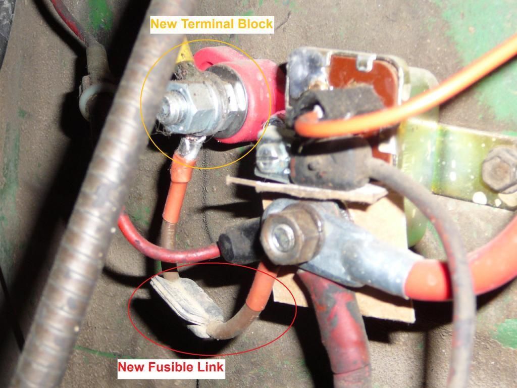
New Terminal Block - I got one online somewhere (bought two, actually). The insulator cap is off for this picture - be
sure to use one because if something touches this post and the chassis or body (ground), sparks WILL fly!


The
New Fusible Link goes from the Starter Relay (large post) to the
New Terminal Block.
The
New Red Wire goes directly to the Ammeter from there (hard to see, but is at upper left of the Terminal Block, with yellow around the ring connector. Goes up by the firewall bulkhead connectors, held by the existing chassis wire clips, and then thru firewall, as pictured in Step #1)
Here's what the Starter Relay area looks like...
 3.
3. As the Service Manual Picture shows, a Fusible Link replaces the original routing of the wires from the Alternator and from the Starter Relay at the Bulkhead connector block. Supposedly, if your fusible link is in good shape, you can just plug it into slot #16. My wiring was a disaster, so I made a new one (got a Fusible Link from NAPA).
 4.
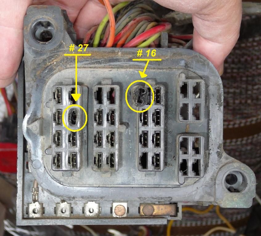
4. Here's where the Fusible Link in step 3 plugs in to... it bridges between (thus connecting) firewall bulkhead terminals #16 and #27. This is important to finish the circuitry and have everything work as intended (as good as - or better - than new!)
I did it this way because I wanted to keep it simple and keep it stock. Wish I'd done this years ago!
Everything works very well - bright headlights, strong heater blower, wipers steady... no more accessory slowness or dim headlights when at a stoplight!
- Walt


