I was asked to start a thread with only the IFS install, so...you asked for it.
When I started looking into adding an IFS to Isaacs truck, I did the normal research I usually do. A google search, read a bunch of articles, watch some youtube videos, and look through parts catalogs. I had never done anything this in depth before. I couldnt weld, but I was familiar with measurements and conversions, and had a good mechanical background. I am an avionics installer, who also does sheet metal fabrication on aircraft for a small completion center. Before this I had re-wired a car, and quite a few helicopters. I had made custom mounts for radios and navigation equipment for lots of aircraft. I have a good electrical background, and I do well reading schematics and blueprints. I learned to weld (barely) along the way, and I am still figuring this out.
I found there was not a lot of information really. There were three basic front suspension ideas; crown vic swap, front clip swap, and the IFS. I didnt want the crown vic because of track width. I didnt want to do the clip swap either. For some reason I landed on the IFS. For the record, I think both the CV swap and the front clip swap would be easier, and way cheaper. I underestimated the scope of this install.
That being said, here is what I know. The problem with these IFS kits is the width of the original dodge frame. Most of the kits ask for “frame width” for choosing the kit you need. This is for the cross member. There seems to be around 4” of play room in the cross member. For example; The welder series kit asked you to choose from three sizes-26-30”, 28-32” and 30-34”. And our frames are 37-½” outside to outside. This directly affects the track width, which on Isaacs truck is 61” with 3” of spacers (1-½” on both sides) or 58” to the wheel mounting surface (The welder series kit says the track width will be 60-½” overall, this is probably because of the A-arms). This has caused a lot of problems (I know I dont have the welder series, but it seems to be typical). The steering rack was too short. The upper A-arms were too short. The shocks hit the frame. The wheels Im using (from my 07 Dodge Charger R/T) are very close to hitting, even with 1-½” spacers in the front. And if you want to run modern wheels, you will have to run spacers. These problems can be overcome. Some are cheap and easy, some are not.
There are a few basic types of IFS, most are based on the 74-78 Mustang II suspension geometry. These only use the geometry in most cases. Some kits do allow you to use some Mustang II parts, like ball joints, A-arms and bushings. The welder series has this option, that is one of the reasons I like it. The 3 basic kits are standard springs, air bags and coilovers, in order of expense. The basic kits come with the spring pockets at the top and a shock mount. Some even have the lateral torsion bars, but it depends on the lower a-arms you use. The airbag kit is next with bag mounts, and some have different ball joints for the extreme angles associated with “laying it out”. And finally, the coil over kit. It seems cheaper, until you add the cost of the shocks. A good shock will be $300 a corner and up. All of these kits can have sway bars added, but most dont come with them. There is a good aftermarket for the MII kits. Oversized brakes, hubs, tubular A-arms, big sway bars, etc. But dont think you are going to be setting track records with a 50 year old design. Its better than a solid axle, but if you want competition grade hardware, find another way. There are several videos on Youtube (I watch a lot of Powernation builds. They have videos with the complete build in them, and they have done a few IFS installs on classic trucks, just not a dodge), and plenty of articles.
Ill attempt to do a few posts, and add pictures and discuss the issues and what I did to fix them, and other ways to fix them. I hope this helps. It might take a few days to get this all together.
One more thing. The ebay, summit and jegs kits are ALL Helix kits. This is chinese garbage. If the kit you are looking at is "hub to hub" and its under $2500, its a helix kit. A good hub to hub should cost over $4k. If you piece it together yourself, you can save money and go a little at a time.
To start with the truck needs the engine out at a minimum. I would say to remove the front fenders also. You might be able to do it with them on, but I wouldnt want to. The cab can stay, and the radiator support can also. You will box the front frame, so remove the motor mounts also (welder series has the motor mounts too). Obviously pull back any fuel lines, wiring and brake lines that are close by. You need a few jack stands, a plumb bob, several levels, and a welder. You can stick, MIG or TIG it in most cases. Mine is both TIG and MIG.
The front suspension needs to come out, but only after you mark the axle center line. This should be in your instructions. I cleaned the frame, and used a plumb bob and a sharpie.
Enough text, Ill post pictures next.
Mustang II IFS install
-
Drummerdad
- Sweptline.ORG Member

- Posts: 379
- Joined: Wed Jan 31, 2018 4:02 pm
- City: gray
- State: TN
Mustang II IFS install
Isaacs truck:
Picture album. https://drive.google.com/drive/folders/ ... sp=sharing
Build thread. viewtopic.php?f=34&t=41915
Picture album. https://drive.google.com/drive/folders/ ... sp=sharing
Build thread. viewtopic.php?f=34&t=41915
-
Drummerdad
- Sweptline.ORG Member
- Posts: 379
- Joined: Wed Jan 31, 2018 4:02 pm
- City: gray
- State: TN
Re: Mustang II IFS install
I think I have enough to get started. Here we go.
Top picture (I get them in reverse order, every time).
The old suspension is out.
2nd picture-The plate and motor mounts. You can keep your old mounts. I cut them flush with the frame to avoid cutting out the stupid rivets. Then weld them back on. I screwed myself, because I left the rest of it behind the plate, and it blocks you from running anything through the frame. If you cut it, remove the part inside the rail.
3rd picture-The plate. It is 3/16 steel. The install instructions should show you where to plate. This is the only place you have to plate, but I went ahead and plated the whole frame.
4th- The parts truck stripped down.
- Attachments
-
-
-
-
Isaacs truck:
Picture album. https://drive.google.com/drive/folders/ ... sp=sharing
Build thread. viewtopic.php?f=34&t=41915
Picture album. https://drive.google.com/drive/folders/ ... sp=sharing
Build thread. viewtopic.php?f=34&t=41915
-
Drummerdad
- Sweptline.ORG Member
- Posts: 379
- Joined: Wed Jan 31, 2018 4:02 pm
- City: gray
- State: TN
Re: Mustang II IFS install
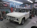
So, the frame was junk in my case, so I had to swap it out. Like I said the cab can probably stay on. I had mine off, but we had to put it on to check the fit of everything.
1st- This is the kit I bought. It was from uncle jimmys jalopys, and I DO NOT recommend this kit. It is a helix kit, which is slang for Chinese garbage that is going to either kill you or make you spend a ton of money fixing the poor quality. Its the same kit sold under a dozen different names. STAY AWAY from this kit. I will discuss the problems as we go.
2nd- this is the start of the fitment. It is very important to make sure you have the ride height set where you want the truck to sit. I misunderstood the instructions (they were horrible anyway), and ended up buying dropped spindles. Isaacs truck will be low, but you can go lower if you want. This crossmember has to be notched to fit the frame. The frame rests on the top of a ledge left by the notch, this sets the ride height. The deeper the notch, the lower the frame sits in the crossmember.
3rd-Now its serious. We have a level on the frame, and two on the crossmember making sure it is square. I used some wooden 1 x 1s to make legs. It worked out okay, but my floor was not level or smooth. Yours wont be either.
- Attachments
-
-
-
Last edited by Drummerdad on Tue Jul 27, 2021 8:30 pm, edited 1 time in total.
Isaacs truck:
Picture album. https://drive.google.com/drive/folders/ ... sp=sharing
Build thread. viewtopic.php?f=34&t=41915
Picture album. https://drive.google.com/drive/folders/ ... sp=sharing
Build thread. viewtopic.php?f=34&t=41915
-
Drummerdad
- Sweptline.ORG Member
- Posts: 379
- Joined: Wed Jan 31, 2018 4:02 pm
- City: gray
- State: TN
Re: Mustang II IFS install
Up until this point it seemed easy. The next steps were just ridiculous. The "top hats" as they are called are supposed to be notched to match the bottom. The installation gives dimensions, but its impossible to get it where it seems right., and the pictures were on an old F100, so it didnt match. I ended up scrapping one of the pieces and having to order another. This is why I think the welder series kit would be the ticket. It comes in separate parts if you like. The cross member, the upper mounts and the shock mounts. I ordered the "corner killer" so it has the coil overs. The shocks in the kit are known to be junk, and everyone said they just bottom out as soon as you put weight on them, so I used them for pictures, and laid them on the shelf where they will stay until I throw them away. I knew I wanted QA1s from the beginning. Thats what makes the coil over kit so expensive.
1st- this is just stupid. If you can find a kit that doesnt require this, buy it. I tried every trick I knew to get this right. After I trashed the one, I figured it out.
2nd- What needs to happen is the upper piece needs to line back up with the lower, like it was a single piece, if that makes sense. After the debacle with the other one, we lined up the three sides and got close. You can swing this and pivot it over the frame and make the shock mount go out further, I guess if you wanted to, but I felt it would mess with the orientation of the a-arms. This is what it needs to be. BUT, this is where the problems start to come into play.
3rd- starting to put the other parts in. I was still figuring it out here, so I hadnt got it exact.
4th- When we got the wheel on, I knew it wouldnt work. I misunderstood the instructions. They tell you to use a set up shock or make your own. Ill have to look up the numbers, but the shocks are sold by ride height. I used the wrong number (overall length versus ride height), and added in 2". But I dont think you can get much lower without the dropped spindles. I put a significant notch in the frame for the steering.
- Attachments
-
-
-
-
Isaacs truck:
Picture album. https://drive.google.com/drive/folders/ ... sp=sharing
Build thread. viewtopic.php?f=34&t=41915
Picture album. https://drive.google.com/drive/folders/ ... sp=sharing
Build thread. viewtopic.php?f=34&t=41915
-
Drummerdad
- Sweptline.ORG Member
- Posts: 379
- Joined: Wed Jan 31, 2018 4:02 pm
- City: gray
- State: TN
Re: Mustang II IFS install
With everything in place, we went forward. I ended up having to cut the motor mounts off, and get new ones. We couldnt weld in between them and the cross member. I also got the dropped spindles, and the truck sat where I wanted it to.
1st- This is the tie-rod notch. If you set the frame lower in the cross member, this notch gets bigger.
2nd-Full lock. This is without the steering rack, which will not go this far. These are 20 x 7 factory Dodge Charger R/T wheels, with a 24mm offset. This is with a 1-1/2" spacer as well. The spindle makes you use the spacer. I think I could get by with a 1/2" spacer and clear the spindle cap. I havent tried.
3rd-Locked the other way. Still without the steering rack. This was to check for frame clearance.
4th- All set in place, and this is where we discovered the shocks will hit the frame. Ill post about this again later. Here you can also see the amount of thread showing on the upper a-arm. There are only about 7 threads inside that tube. Thats just not enough.
- Attachments
-
-
-
-
Isaacs truck:
Picture album. https://drive.google.com/drive/folders/ ... sp=sharing
Build thread. viewtopic.php?f=34&t=41915
Picture album. https://drive.google.com/drive/folders/ ... sp=sharing
Build thread. viewtopic.php?f=34&t=41915
-
Drummerdad
- Sweptline.ORG Member
- Posts: 379
- Joined: Wed Jan 31, 2018 4:02 pm
- City: gray
- State: TN
Re: Mustang II IFS install
In the end, I like the IFS, just not this one. Ill probably put an IFS on the 67 F100, but its going to be a welder series. I didnt know there were so many options available. If you want to do this, watch some videos on you tube, and shop around. Figure out what you want. Airbags, coilover or springs? Stamped factory a-arms, tubular a-arms, or fully adjustable race grade a-arms? 15" brakes or 9-1/2" brakes? Power steering or manual? There are plenty of options. Ill post more tomorrow. And answer any questions when I can. Hope this is helpful.
Isaacs truck:
Picture album. https://drive.google.com/drive/folders/ ... sp=sharing
Build thread. viewtopic.php?f=34&t=41915
Picture album. https://drive.google.com/drive/folders/ ... sp=sharing
Build thread. viewtopic.php?f=34&t=41915
-
soopernaut
- Sweptline.ORG Pioneer

- Posts: 8931
- Joined: Wed Dec 31, 1969 6:00 pm
- Location: Des Moines,IA
Re: Mustang II IFS install
Good thread. I've read about all the issues you've had in your build thread. All those new parts look nice, but if they don't work it really doesn't matter.
Another suspension that isn't mentioned much here is the Ford Aerostar. Since you have a Ford truck, I figured you are familiar with it or should at least know about it. I've seen a couple in Sweptline trucks, but there is relatively little information here. A quick search tells me the Aerostar frame is 38 inches wide and has a 62" wheel to wheel measurement. Someone said it is almost a bolt in procedure other than the steering rack pointing nearly straight up.
I went with the frame splice. What was the reason you didn't want to use this method?
-
Drummerdad
- Sweptline.ORG Member
- Posts: 379
- Joined: Wed Jan 31, 2018 4:02 pm
- City: gray
- State: TN
Re: Mustang II IFS install
I havent heard about the Aerostar swap. I have heard about a Jaguar swap, but didnt look too much into it either. I didnt do the CV swap because of wheel fitment, and the track width. I didnt do the Jaguar because of the unknown. There arent that many out there, and I didnt know about part availability. As for the newer truck frame clip, I didnt know if I could get a frame at that point, and I didnt want to cut the frame...again. I had to cut the frame to shorten it, and I didnt feel it was good to cut it yet again in the front. Some people might not agree and argue with me, and thats fine. I didnt say it was a solid excuse.
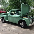
Knowing what I know now, I think I would have went the front clip route. Im not sure if it goes low enough, but I cant see it being worse than this IFS. SO, while we are talking about it, it would be a good time to show you how NOT to do a frame clip swap. I bought Isaacs truck and didnt really look at it enough. We fell in love with it without really investigating the work.
1st-Bonus picture. Its not the front suspension, I know, but its ugly. I dont know what goes through a persons mind to make them do this, but I guess thats a good thing. I look at this, and all I can say is "why?"
2nd- This is the frame after it was removed. There were so many problems. The driver side upper control arm had been relieved for the steering shaft. The springs were cut. The frame wasnt even (look at the curve going out to meet the wider earlier frame rails), the welds were horrible, he cut the frame straight, so many problems.
3rd-The splice. I couldnt believe this guy sold me a truck, he knew my son was going to drive, with this in it. You could see right through most of the splice.
4th-This is a "cab mount" or at least it identifies as one. We actually stepped on one, and it fell off. If you look closer, at the front there was another splice, for some reason. This is the splice I saw that made me remove the frame. I couldnt see the other splices.
- Attachments
-
-
-
-
Isaacs truck:
Picture album. https://drive.google.com/drive/folders/ ... sp=sharing
Build thread. viewtopic.php?f=34&t=41915
Picture album. https://drive.google.com/drive/folders/ ... sp=sharing
Build thread. viewtopic.php?f=34&t=41915
-
Drummerdad
- Sweptline.ORG Member
- Posts: 379
- Joined: Wed Jan 31, 2018 4:02 pm
- City: gray
- State: TN
Re: Mustang II IFS install
Now for the issues.
This Helix kit, from Uncle Jimmys Jalopys, has to be the worst kit available. Its the same kit you will get from ebay, and summit and jegs....maybe walmart too.
The frame being so wide causes many issues, but the kit has its own issues. Ill cover the issues caused by the frame width first. You will probably have these issues with any kit on these trucks, unless you have a kit built. There are companies who will custom build a cross member and MII kit, but its about $5k and up. You can also get a custom frame. From what I can tell, without requesting a quote, that starts at about $12k, and goes to almost $20k for a roller.
The frame rail will sit on the outside of the cross member making the shocks hit. I have QA1s, but the springs are a common size. They are advertised at 2-1/2" ID, but they measure at 3.7" OD, give or take. You might be able to get smaller diameter springs, Im not sure. If you want airbags, that a different story, as the bags are probably bigger than the springs. Just something to consider. As far as I can see, the easiest way to fix this is with longer shock mounts, so thats what I did. You might not have this problem with other kits or different shocks. If you get the standard MII kit, with the springs and shocks in a cup style mount, this might not happen.
The upper A-arms were short. There were only 4 or 5 threads going into the arm on both ends. I know it would change slightly, because I had the wheels set perfectly level, but they wouldnt come in enough after setting my caster angle to make me happy. So I extended them by about 1/2", by adding threaded tube ends.
The steering rack was also short. There are a few lengths of tie rod ends. As far as I can tell, the ones that came with this kit are the longest available. And I couldnt find any longer. So I extended them also. I plan on building a custom tie rod extension, with L/H and R/H ends to make toe adjustments easier.
Wheel fitment is an issue, because of the spindle. I want to run a wider, Hellcat style wheel, because Isaac was obsessed with the hellcat. The problem is, Dodge wheels get a more positive offset ( more backspacing) when they get wider, as most modern wheels do. So if you go 2" wider, almost all of that is to the inside of the wheel. Up front this is a real problem. You can see in the pictures above, the wheels are close to hitting the frame. I could get negative offset wheels, but they dont make Hellcat style wheels in a negative offset, and they are expensive. I planned on fixing this with longer A-arms, but I dont know if that can happen. Im still rolling this one around in my head. I want to make a frame later (in a few years) and if I do, I can go with C5 suspension parts, which can be wide enough to push the wheels out where I want them. Its just a thought right now.
1st-The shock hitting. If the frame was 2 inches overall, or 1" per side, it would probably be okay.
2nd-This is what I did to the A-arms. I cut about 1/2" out, because the tube ends were about 2" long.
3rd- The tie rod end. I just ordered some threaded bungs from ebay that went on the steering rack, and welded them on. Ill build a complete set later, unless I build that complete frame I want to build.
4th- Just imagine the wheel being 2" wider, on the inside. The inside lip of the wheel would be past the ball joint. Its an issue you will run into trying to get modern wheels on these trucks no matter what. Most of the new wheels have +18 to +25 and even +30mm offsets. You need like a -25 to run a 9" wheel up front. The back is easy. You can get custom offset wheels, but most are ugly, and they get expensive. I have seen some for $1800 a wheel.
- Attachments
-
-
-
-
Isaacs truck:
Picture album. https://drive.google.com/drive/folders/ ... sp=sharing
Build thread. viewtopic.php?f=34&t=41915
Picture album. https://drive.google.com/drive/folders/ ... sp=sharing
Build thread. viewtopic.php?f=34&t=41915
-
Drummerdad
- Sweptline.ORG Member
- Posts: 379
- Joined: Wed Jan 31, 2018 4:02 pm
- City: gray
- State: TN
Re: Mustang II IFS install
Now for the issues with this kit in particular.
The helix kit is from the Hoffman group if memory serves me correctly. Just google Helix suspension problems, and read to your hearts content. The main issue is of course, quality. The chinese have a way of making things cheap for sure, and it usually comes with a quality risk. The specific problems are; poor welds, low quality materials, untraceable parts, and non-matching parts.
Poor welds- Some of them look like bubble gum has been smeared around them. On the A-arms I have considered just building my own altogether. The cross member seems beefy enough, but the A-arms look questionable, especially after seeing some of the quality arms available and seeing quite a few poor quality welds of my own. Im still on the fence on this. I want new arms, and it wouldnt be out of my ability to make some that are better. But I dont want to spend the time and money to make them for this, if they wont work in the future. At a minimum, Im going to cut this out and replace it eventually. I want to make a new frame. I dont think the A-arms will work on another kit. Some people have had problems with the lower a-arm supports breaking, so we beefed those up with a large gusset.
Low quality materials- Everything is built cheap, even the metal seems of a lesser quality than I am seeing in steel I have bought locally. It is probably a different alloy, but it seems soft. The Ball joint were bad out of the box, and two of the rubber boots were ripped. The bar ends and bushings look cheap, and have some rust on them. The shocks...I cant even begin to explain the shocks. The ends screw on, and the collar is loose. It feels like it would just shatter if I put the truck weight on it, especially compared to the QA1s.
Untraceable parts- Perhaps the most irritating part is the fact they went out of there way to remove part numbers and identifiers to help you service this suspension in the future. I dont know how long a ball joint is supposed to last, but they go out. And I cant find anyone to identify these ball joints. Of course, you can purchase another ball joint directly from Helix, for $90 each. I can get 4 K772 ball joints and the sleeves to fix these a-arms for $100. The bar ends and bushings are easy enough, but what about the brakes? Ill need new pads eventually, so how about a little note telling me what parts number I need to replace it with. This kit came without a bill of materials, a packing list or even a list of parts in any shape or form. Shady.
Non-matching parts- I remember when I screwed up the top hat, and called for a replacement, the guy on the phone said he would get me one off the shelf. I think this is why my two sides dont match. The instructions tell you to lay them on a flat surface, and make sure they match both ways. That tells me there are differences (sometimes) in these parts. If you look at the A-arms closely, they are slightly different. Not the position of the main points, but the position of the arms in relation to the ball joint sleeve is slightly off. The lower A-arms had two square bars on them for bag mounts, and they were a bit off too. This is not a big deal, as Im not using the bag mounts, and I cut them off anyway.
There are other issues. Like the fact there is no caster adjustment built in to this kit. The steering rack was challenging as well. Its a manual rack and pinion. The universal joint sent with the suspension didnt fit. I bought some from Speedway, but it didnt seem right either. I spent several hours looking into it and measuring to make sure, and ordered more U-joints...and it didnt fit. Either the u-joints were off (unlikely, because I bought several different brands) or the rack was a bit off. So, I put the one that was close in a vice and crushed it a little. Then it went on and felt good. I figured if it didnt feel right, I would weld it. So far it feels okay.
I think thats about it. The bolts with the kit were good and they are grade 5, and they have nylon lock nuts with them, which is good. Thats about the only good thing I can say about it. My intention is to remove it or replace it at a later date.
Sorry this is so wordy. I dont have a lot of pictures on some of this. If anyone has questions, Ill try and answer.
Isaacs truck:
Picture album. https://drive.google.com/drive/folders/ ... sp=sharing
Build thread. viewtopic.php?f=34&t=41915
Picture album. https://drive.google.com/drive/folders/ ... sp=sharing
Build thread. viewtopic.php?f=34&t=41915
-
Drummerdad
- Sweptline.ORG Member
- Posts: 379
- Joined: Wed Jan 31, 2018 4:02 pm
- City: gray
- State: TN
Re: Mustang II IFS install
If I were to do this today, knowing what I know now, I would do the Welder Series kit, with QA1s. I dont know what A-arms I would use, but there are several available from many different sources, from stamped factory replacements to fully adjustable tubular stuff. Here are a few pictures.
For what its worth, Im considering doing this kit on the F100 next. Itll be a basic kit, nothing fancy. I wont use stamped a-arms, but itll be middle of the road parts, small disc brakes, normal stuff.
1st-Just some basic a-arms. Nothing fancy. These are about $500 for uppers and lowers.
2nd-The coil over Welder Series kit. I dont really like the upper shock mount, but the rest is nice.
3rd-The bare kit. You can get it several ways, and piece by piece if you are on a budget.
4th-This is about what I plan on installing in the Ford. You can get QA1s that go in the cup style mounts also. I didnt know that. I probably wont get QA1s on the Ford. This picture shows the standard MII caster and camber adjustments. The pivot shaft and the mounts are slotted.
- Attachments
-
-
-
-
Isaacs truck:
Picture album. https://drive.google.com/drive/folders/ ... sp=sharing
Build thread. viewtopic.php?f=34&t=41915
Picture album. https://drive.google.com/drive/folders/ ... sp=sharing
Build thread. viewtopic.php?f=34&t=41915
-
Series1Utiline
- Sweptline.ORG Member
- Posts: 132
- Joined: Sat Feb 18, 2017 2:08 pm
- City: Newberg
- State: OR
Re: Mustang II IFS install
Just curious what the distance ended up being between your frame boxing plates? (the dimension that dictated your cross member width)
-
Drummerdad
- Sweptline.ORG Member
- Posts: 379
- Joined: Wed Jan 31, 2018 4:02 pm
- City: gray
- State: TN
Re: Mustang II IFS install
Series1Utiline wrote: ↑Fri Jul 30, 2021 6:30 amJust curious what the distance ended up being between your frame boxing plates? (the dimension that dictated your cross member width)
I didnt measure the inner dimension. The outside to outside frame width determines the cross member width, at least on this kit and the welder series kit. The suspension was only too wide because the outside surface of the frame, so if you wanted, you could narrow the frame width (reduce the thickness of the frame rail by an inch each side) or joggle the frame inward at this point (this would require removing the front frame cross member at the radiator support), or even install a vertical c-notch and make a spring/shock pocket.
Technically speaking, you can get whatever track width you want the front suspension to be, and just narrow the frame to match forward of the cab. It would be a chore, but it is possible.
Isaacs truck:
Picture album. https://drive.google.com/drive/folders/ ... sp=sharing
Build thread. viewtopic.php?f=34&t=41915
Picture album. https://drive.google.com/drive/folders/ ... sp=sharing
Build thread. viewtopic.php?f=34&t=41915
-
swptln
- Sweptline.ORG Member
- Posts: 457
- Joined: Tue Oct 02, 2012 8:31 pm
- City: East Brookfield
- State: MA
- Location: Massachusetts
- Contact:
Re: Mustang II IFS install
WOW!!, talk about some serious modifications to a kit. Holy Crap....you have more patience than I have.....I surely wouldn't deal with all that.
Should have done this:
https://dodgesweptline.org/phorum/read.php?2,12455
Should have done this:
https://dodgesweptline.org/phorum/read.php?2,12455
Mark D.
61-71 Dodge Truck Association
http://www.sweptlinesunlimited.com
1968 W200 Sweptline
1969 D100 Utiline
1993 D250 Club Cab
61-71 Dodge Truck Association
http://www.sweptlinesunlimited.com
1968 W200 Sweptline
1969 D100 Utiline
1993 D250 Club Cab
-
Drummerdad
- Sweptline.ORG Member
- Posts: 379
- Joined: Wed Jan 31, 2018 4:02 pm
- City: gray
- State: TN
Re: Mustang II IFS install
swptln wrote: ↑Fri Jul 30, 2021 1:46 pmWOW!!, talk about some serious modifications to a kit. Holy Crap....you have more patience than I have.....I surely wouldn't deal with all that.
Should have done this:
https://dodgesweptline.org/phorum/read.php?2,12455
And Im not done. I have new ball joints and sleeves on the way, so Ill end up cutting these things in half, and adding the new ball joint sleeves. I thought about just remaking the whole a-arms, but I dont want to make them for this suspension, when Im sure its coming out later.
Isaacs truck:
Picture album. https://drive.google.com/drive/folders/ ... sp=sharing
Build thread. viewtopic.php?f=34&t=41915
Picture album. https://drive.google.com/drive/folders/ ... sp=sharing
Build thread. viewtopic.php?f=34&t=41915
-
Series1Utiline
- Sweptline.ORG Member
- Posts: 132
- Joined: Sat Feb 18, 2017 2:08 pm
- City: Newberg
- State: OR
Re: Mustang II IFS install
Those that I have done had the cross member width established by the inside dimension of the frame as that's were it is attached and welded. The outside is simply where the spring hats go. This allowed a given cross member to fit any car or truck by trimming the length as provided by the manufacturer. No need to narrow the frame. I understand yours was not designed this way.Drummerdad wrote: ↑Fri Jul 30, 2021 7:40 amSeries1Utiline wrote: ↑Fri Jul 30, 2021 6:30 amJust curious what the distance ended up being between your frame boxing plates? (the dimension that dictated your cross member width)
I didnt measure the inner dimension. The outside to outside frame width determines the cross member width, at least on this kit and the welder series kit. The suspension was only too wide because the outside surface of the frame, so if you wanted, you could narrow the frame width (reduce the thickness of the frame rail by an inch each side) or joggle the frame inward at this point (this would require removing the front frame cross member at the radiator support), or even install a vertical c-notch and make a spring/shock pocket.
Technically speaking, you can get whatever track width you want the front suspension to be, and just narrow the frame to match forward of the cab. It would be a chore, but it is possible.
-
my5thmopar
- Sweptline.ORG Pioneer
- Posts: 1003
- Joined: Thu Aug 08, 2013 8:51 pm
- City: Columbia
- State: TN
Re: Mustang II IFS install
Great thread. Thanks for sharing your experience. Craig
1964 D100 Utiline
2019 Ram Classic
viewtopic.php?f=34&t=36025&hilit=build
viewtopic.php?f=34&t=40251
2019 Ram Classic
viewtopic.php?f=34&t=36025&hilit=build
viewtopic.php?f=34&t=40251
-
welderseries
- Sweptline.ORG Member

- Posts: 10
- Joined: Fri Aug 19, 2016 7:43 am
- City: Breslau
- State: Foreign
Re: Mustang II IFS install
Sorry for the bump, but I wanted to say thanks for looking at our parts and for such a detailed thread.
I also thought I should mention that we do have a 62-1/2” track width crossmember which works great on a Sweptline (like my 68). When we say “track width”, we refer to the wheel mounting surface to wheel mounting surface on the rotor. Different rotors can change this dimension. The frame outside dimension is less critical but still somewhat important. The 62-1/2” track width kit requires 4” of rack spacers on the passenger side, and 2” on the driver side. We offset the rack so it’s closer to the driver side frame rail to help with steering linkage clearance.
We do have a worksheet that you can fill out with your frame dimensions, and we’ll provide you with the crossmember and tower cut lines.
Again, thanks for mentioning us. I hope we can help with parts in the future (or maybe we already have, this thread is from a few years ago :) ).